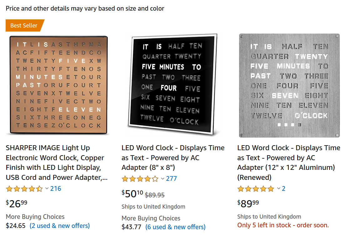
A few years ago I came across a clock design that I hadn’t seen before. I thought the design was pretty cool and I wondered how hard it would be to build a webpage that would display similar wording that highlights to display the current time.
I got to work hacking around, figuring out how to translate time in numbers to time in text. After a couple of hours I had something I was fairly happy with.
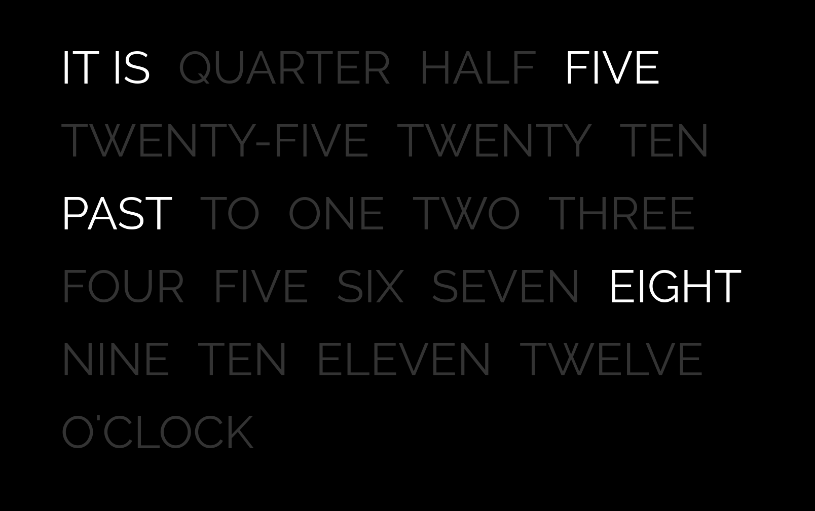
You can see the live version here and the code here.
Flash forward 5 years, having recently found an interest in electronics, I thought to myself: “I want to build a clock”, not only for the learning experience but also because I could do with a clock.
I spent a couple of weekends designing, building and soldering together different parts and this is what I came up with:
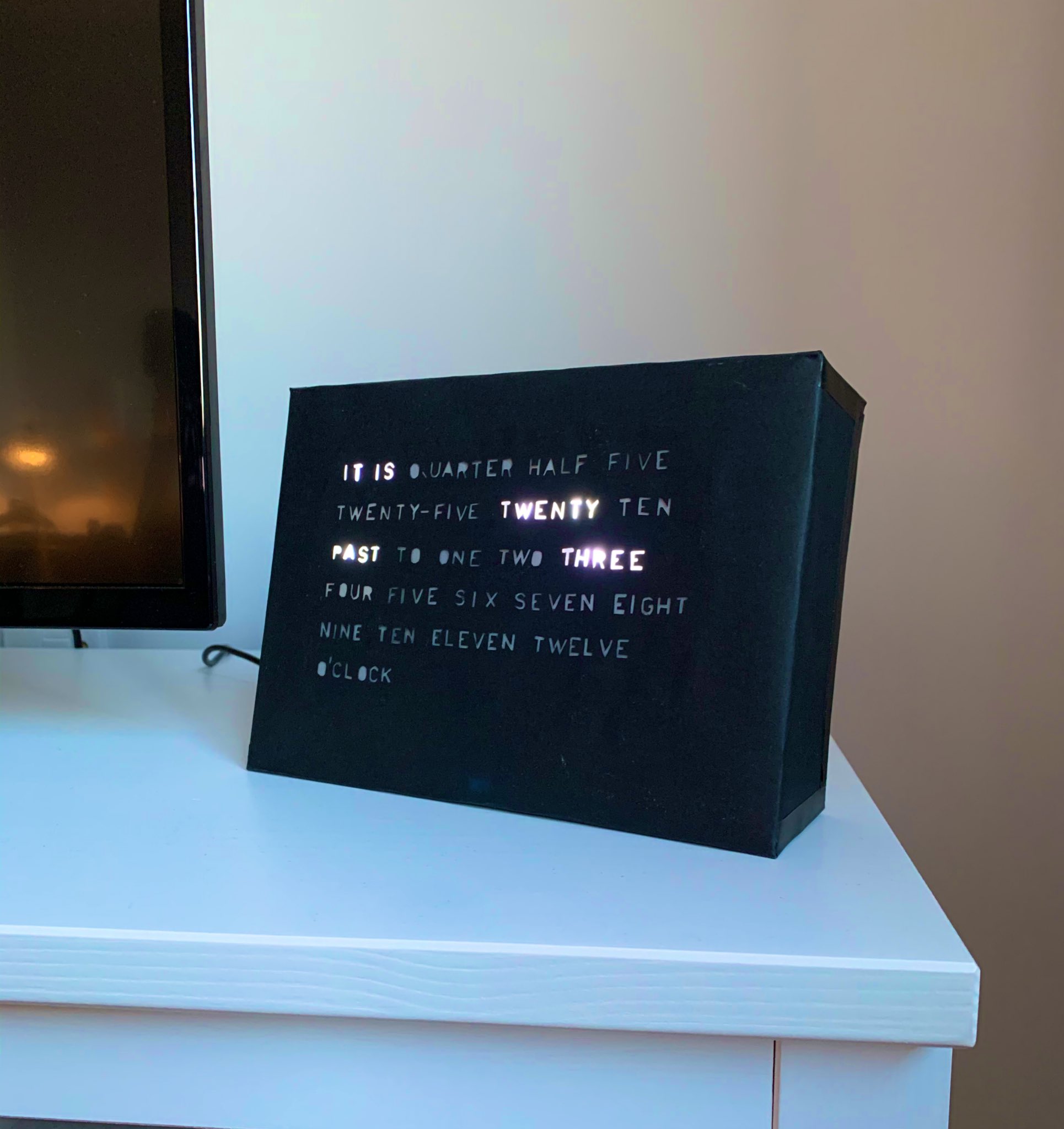
The following sections discuss different parts of the clock, how each part was built, what I learnt and what could be improved.
The circuit design
The first step was to think about how the circuit would work. At this early stage, I knew I needed at least twenty-two LEDs: an LED to light up each word. “It is” was treated as a single word as there are only four characters and they are always lit. I first broke the words down into different groups:
Group A: it is
Group B: five, ten, quarter, twenty, twenty-five, half
Group C: to, past, o’clock
Group D: one, two, three, four, five, six, seven, eight, nine, ten, eleven, twelve
You can take one word from each group and string them together into a sentence: “it is five past ten” or “it is twenty-five to three”. The only exception is that you do not pick an option from Group B when “o’clock” is picked from Group C: “It is four o’clock”. I then had to figure out how to individually address twenty-two LEDs with only twenty addressable pins on the Arduino. I researched around and came across a technique called Charlieplexing.
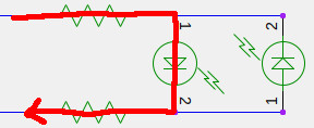
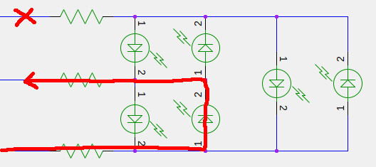
Charlieplexing exploits the diodic nature of LEDs, that is, LEDs only allow electricity to flow in a single direction.
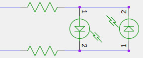
The above image shows two LEDs in parallel, both aligned differently such that their cathodes and anodes are opposite each other.
If we connect the two circuit inputs to Arduino pins and set the top input to HIGH and the bottom input to LOW the left LED will light up:
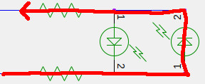
If we set the top input to LOW and the bottom input to HIGH the right LED will light up:
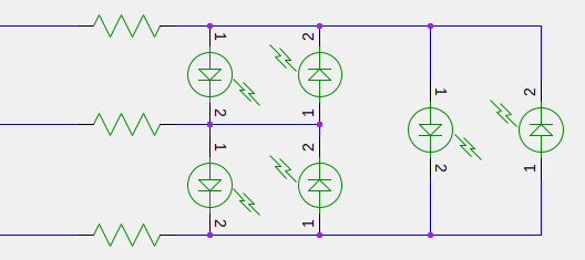
If we connect more inputs and more LEDs we can create a matrix of individually addressable LEDs:
If we set the top input to HIGH, set the middle input to LOW and disconnect the bottom input, the top-left LED turns on:
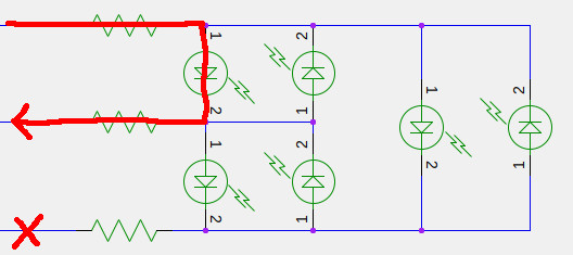
If we disconnect the top input, set the middle input to LOW and set the bottom input to HIGH, the middle-bottom LED turns on:
By controlling which output pin on the Arduino is set to HIGH, which output pin is set to LOW and which output pin is marked as an input (essentially disconnecting it from the circuit) you can individually address LEDs in the matrix.
One downside to Charlieplexing is that you can only have 1 LED on at a time. Setting two inputs to HIGH and one input to LOW produces weird outcomes. This “1 LED at a time” thing wasn’t going to be an issue though, because I could create 2 individual Charlieplexed circuits: a circuit for Group D and circuit for Group B. Group A is always lit so I’ll connect that directly to 5v and ground. Group C only has 3 words in it so I’ll connect each of those to a pin on the Arduino and ground.
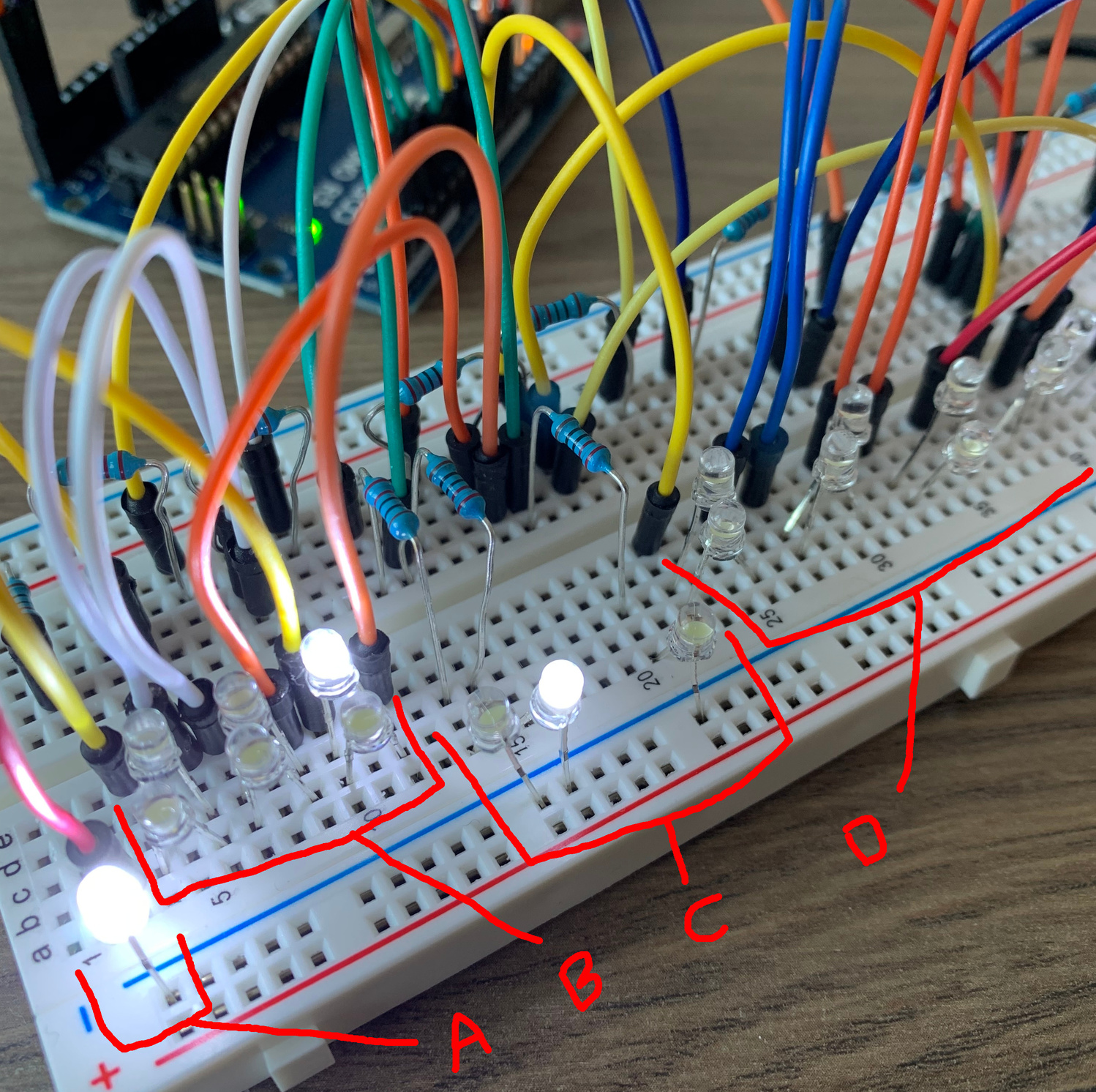
As a reminder, these are the word groups:
Group A (connected to 5v): it is
Group B (Charlieplexed): five, ten, quarter, twenty, twenty-five, half
Group C (each connected to a pin on the Arduino): to, past, o’clock
Group D (Charlieplexed): one, two, three, four, five, six, seven, eight, nine, ten, eleven, twelve
I got started writing code and mounting various components into my breadboard:
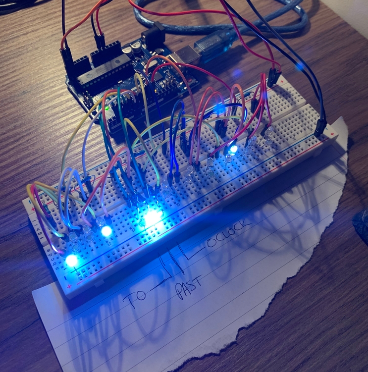
Given an hour between 0 and 23 and a minute between 0 and 59, the Arduino would work out which LEDs to light up in each Charlieplex and change the outputs respectively. One thing I hadn’t put much thought into yet was how to keep track of time, but I’ll cover that point later on.
If you want to learn more about Charlieplexing this article is great.
The face
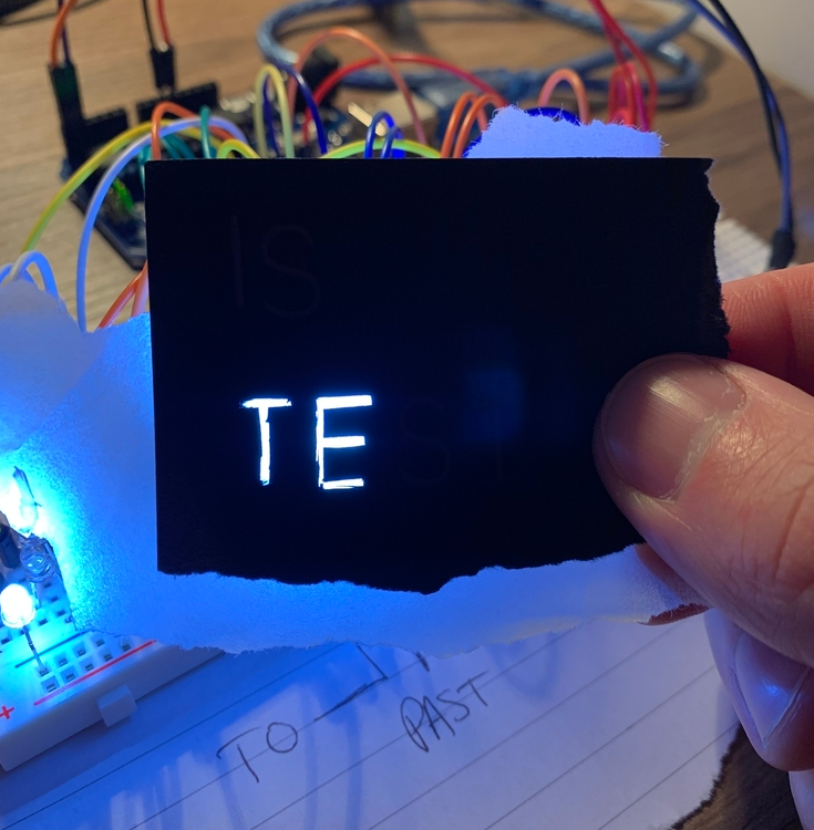
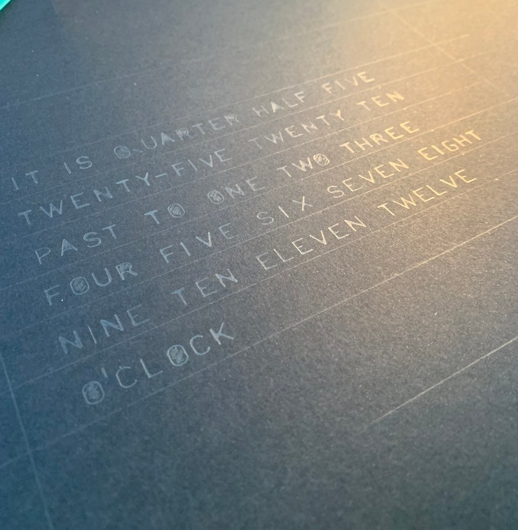
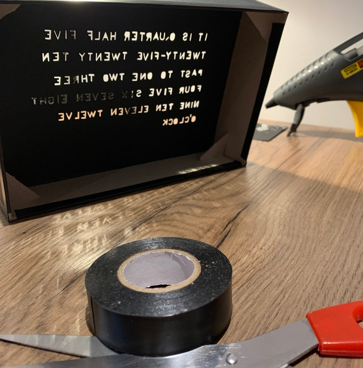
I had a prototype circuit working so I got started on the face of the clock. I picked up some tracing paper and some black paper, cut a couple of test letters into the black paper and held the tracing paper behind the cut letters so that the light was diffused through the gaps:
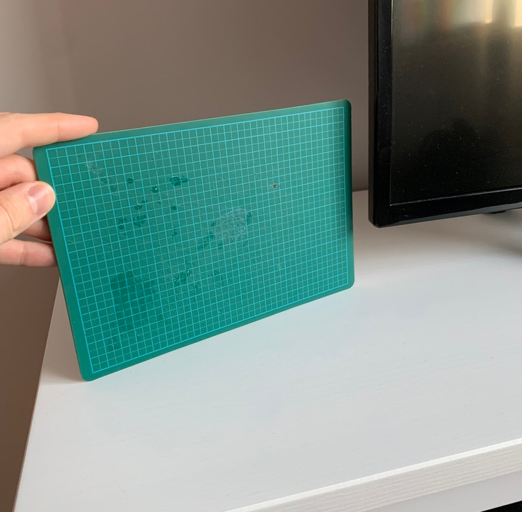
This seemed to work pretty well so I went with it. I knew that I wanted the clock to be about the size of my small cutting board. I drew around the cutting board to help me estimate how much space I would have to fit the letters in and got to work stencilling.
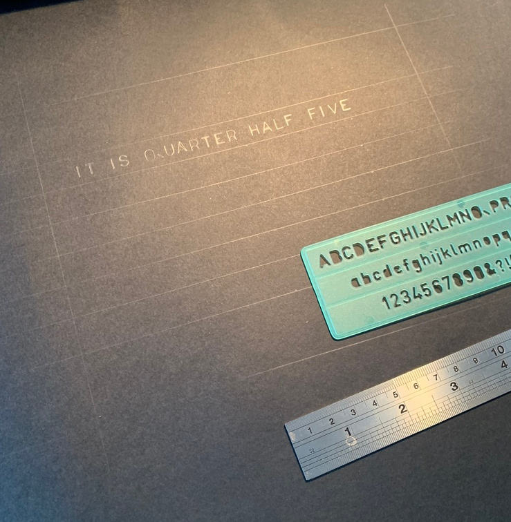
After the letters were down on paper I took a sharp blade and cut out the letters.
The frame
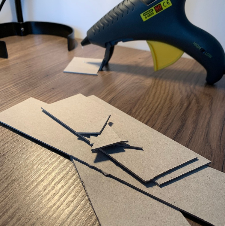
Once I had the face sorted I had to work out how to mount it. I cut off four pieces of sturdy card and glued them together, using triangle pieces to help with stability. I added a slight angle to the bottom of the frame so that the clock sort of leans back a bit when it’s stood up.
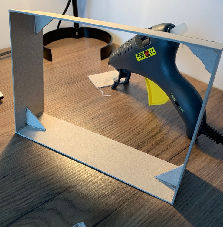
I was pretty happy with the outcome and decided that there would be enough space for all of the electronics to fit within the frame. I carefully mounted the clock face onto the frame, using some black insulation tape to neaten up the edges:
Now I had to figure out how exactly I was going to mount the LEDs behind each word, keeping in mind that I didn’t want the light to bleed across words.
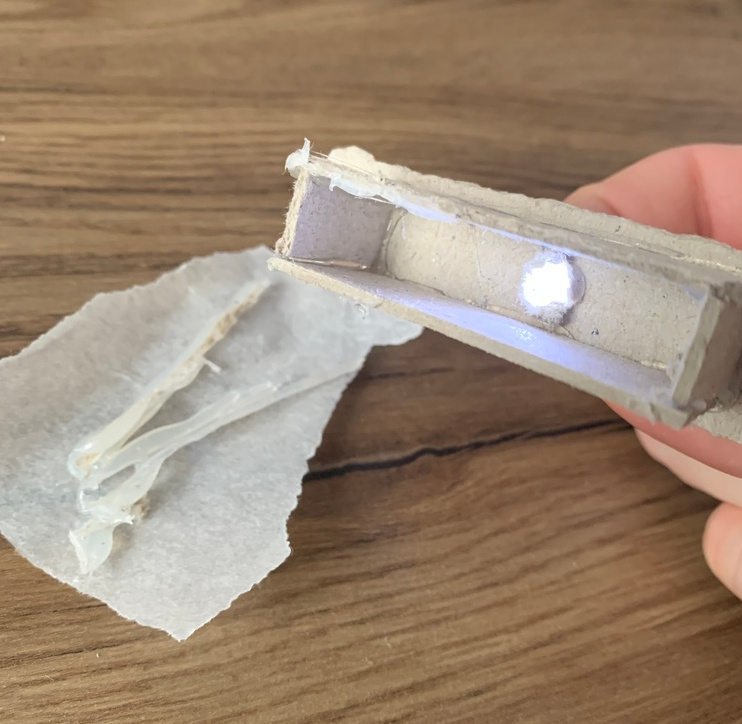
I built a small “prototype LED box thing” that housed an LED, covered it with some tracing paper and held that behind a word on the clock face:
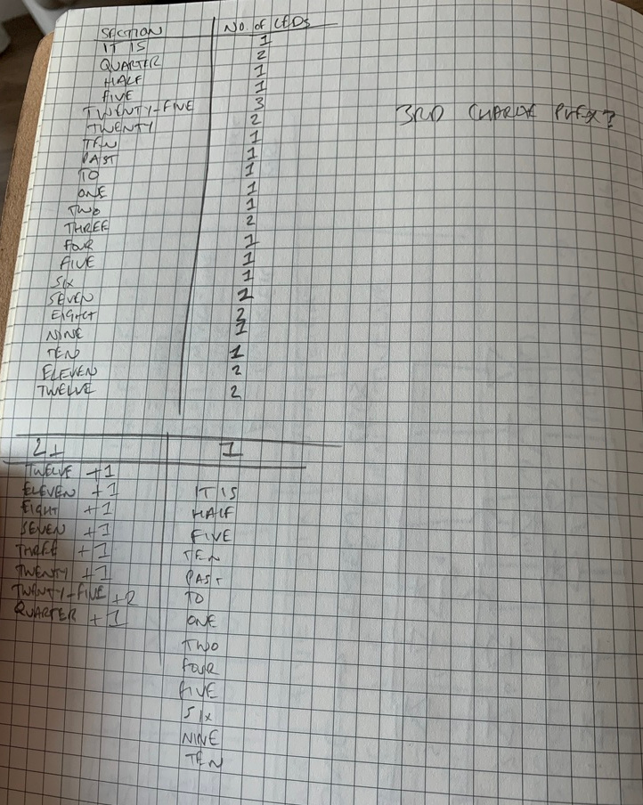
After some experimentation, I realised that 1 LED behind each word wasn’t going to cut it, especially for the longest word “twenty-five”. The light from the LED was not spreading out enough within the box. To try and fix this I decided to add more LEDs. I scribbled down which words would need an extra LED and worked out that I could probably fit all these extra LEDs into a separate Charlieplex.
Regrettably, I rushed through this decision too quickly and missed a couple of things, but we’ll explore those in more detail later on. I knew I roughly had enough pins to achieve what I wanted and the worst case was that I only end up with 1 LED behind each word, which works fine, it just doesn’t look as good.
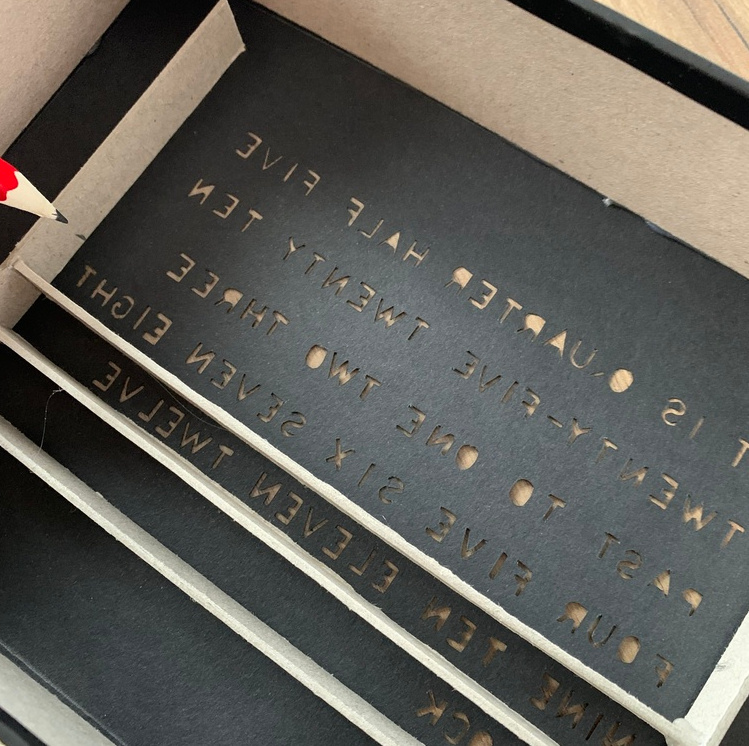
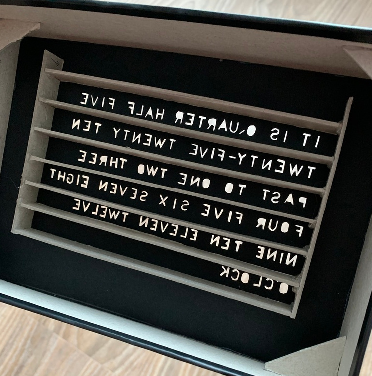
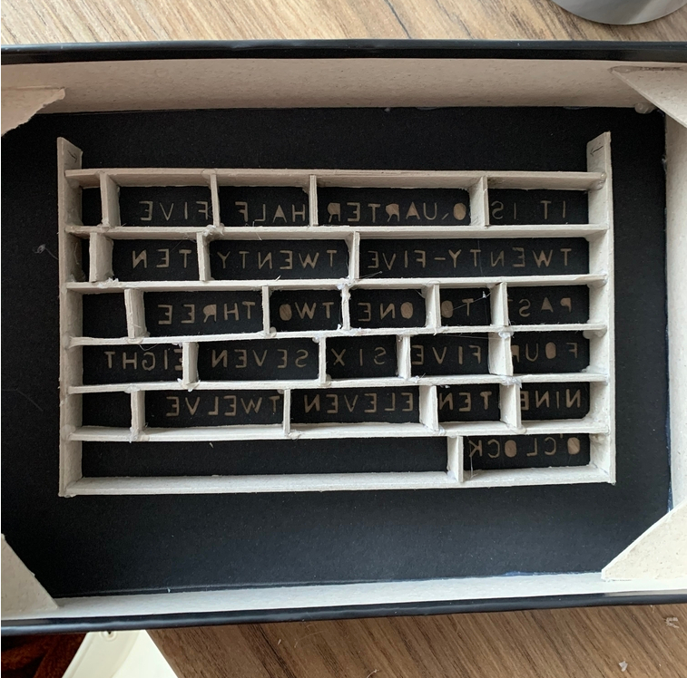
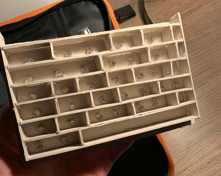
I had an idea in mind for the internal LED frame so I got started on that. I cut out some rectangular pieces of card and used them to start building up the internal frame, positioning them based on how the words sat on the clock face:
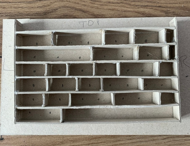
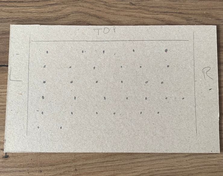
Once the internal LED frame was built I mounted it onto a sheet of card and worked out where the LEDs should sit, making holes for them with a screwdriver, and glueing the LEDs in place:
Tracking time
One thing that I hadn’t solved yet was how to keep track of time. Whilst building the frame and the clock face in the back of my mind, I had this scattered idea that I could maybe count the number of seconds since the Arduino was plugged in or something… and then to change the hour and minutes I would have two switches… having it always start at midnight… but the more I thought about it and researched it as an option the less suitable it felt. I remembered that my Arduino starter kit came with a clock module, labelled “DS1307”, which looks a bit like this:
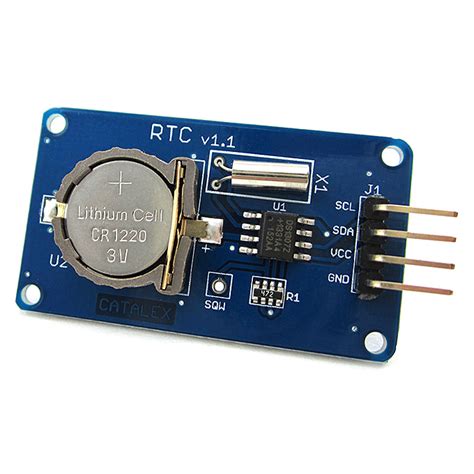
These are handly little modules that fairly accurately keep track of time using a crystal oscillator. If the module loses power it falls back onto the lithium cell battery and keeps on counting the seconds. This meant that I could unplug the clock and still have the time running in the background.
I researched how to wire this module up to the Arduino and what library I needed to communicate with it. It didn’t work. For some reason, I kept getting “15:34:00, May 9th 2918” or something out of the module. I tried to set the time on the module but that didn’t work either.
I searched around on different forums and after trying lots of different code examples it still didn’t work. I assumed that my module was broke in some way. I checked the battery but that had power so it wasn’t that. I left the module for a bit and researched how easy it was to build a clock circuit myself. It turns out that it wouldn’t take too much effort but I didn’t have many of the parts so I decided to go back to the module and try one more time. I came across some example code online that used a different library written for a DS3231 module. I thought “what the heck” and ran it. It worked, which was weird but I didn’t question it. I had a working clock. I set the time on the module, made changes to the code where I needed and that was that. I think they might have used the wrong chip on the module or something, I’m not too sure but I had a working clock so I didn’t give it much more thought.
The wiring and final assembly
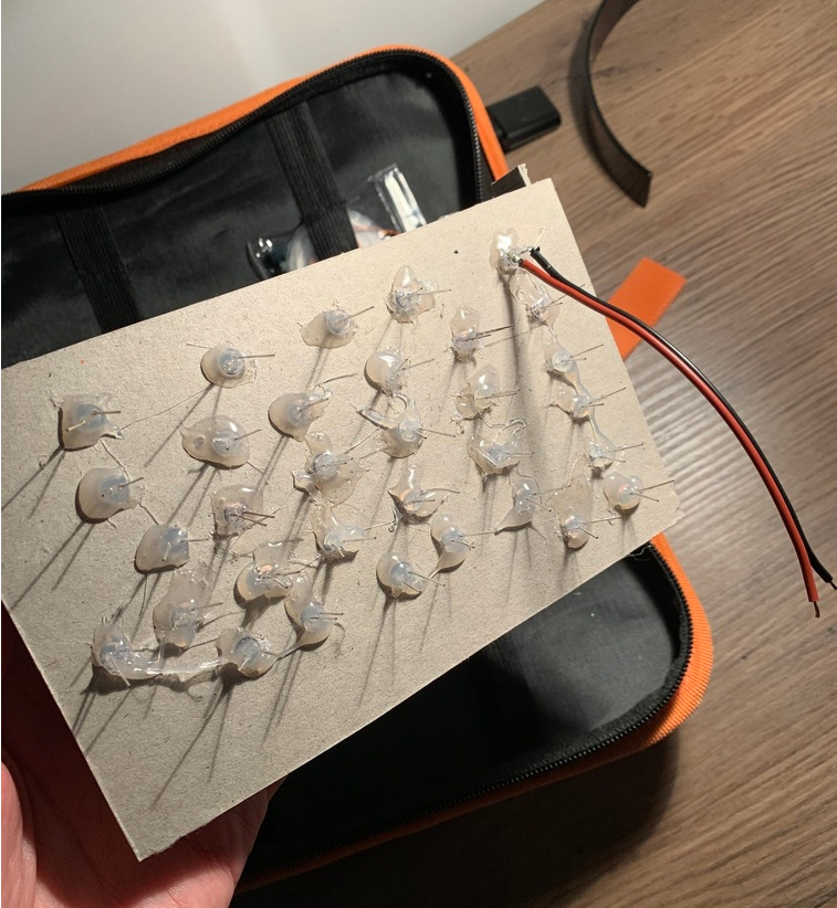
It was time to wire everything up, starting with the LEDs. Each leg of the 32 LEDs needed a wire soldering to them. I also decided to wire up the first Charlieplex, which was Group D (all of the hours), to get an idea on how it would all fit together.
Soon after starting I realised the wire I had wasn’t the best type of wire for the job. It was too thick and heavy but it was the only corded wire I had. To be fair, it wasn’t terrible.
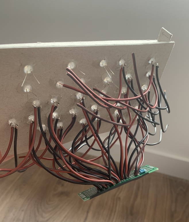
I stuck on a podcast and got on with the rest of the soldering. After a few hours and a couple of breaks, I had all of the wiring completed. I stuck down some tracing paper to the back of the clock face and mounted the LED frame. One mistake I made (that I’ll point out now) was that I soldered up most of the LEDs with similar lengths of wire, not thinking about how they all wire up with each other; some wires have to travel further than others. This lack of forward-thinking led to a bit of a mess… but a working mess:
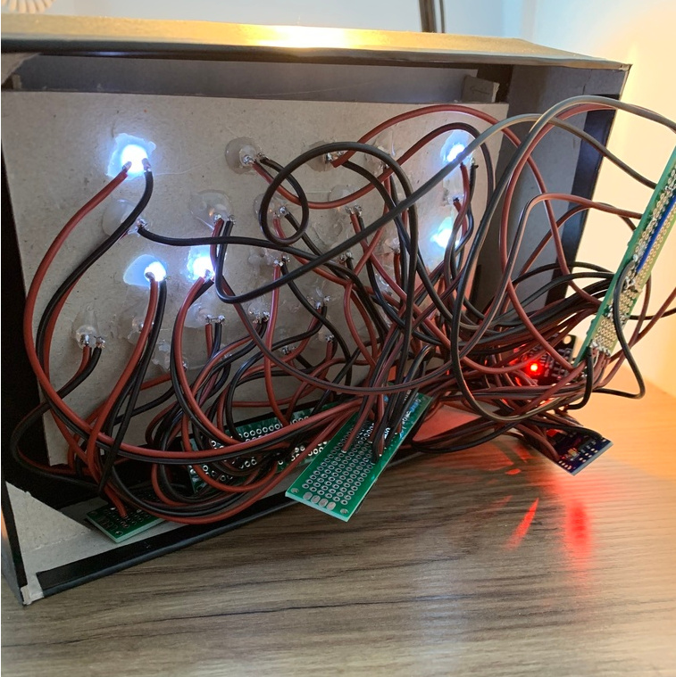
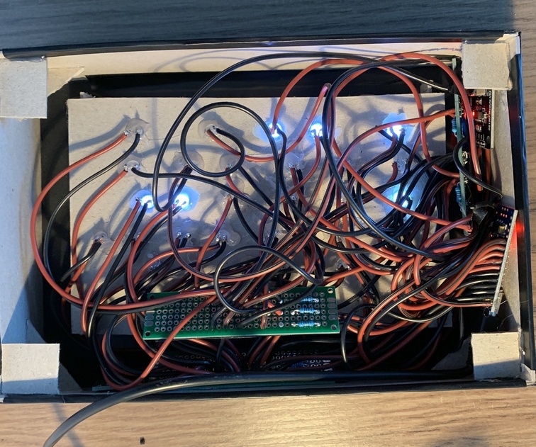
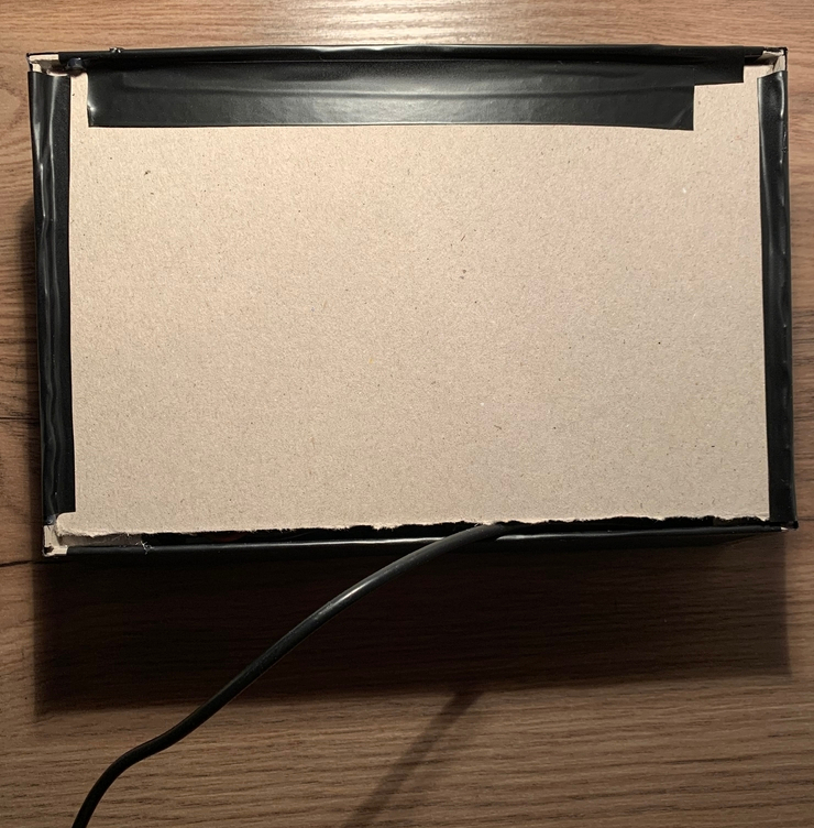
The last thing to do was to cram all the wires into the frame and stick on the backplate:
What I learnt
This project was started and finished to satisfy two equally valued goals:
- to learn
- I wanted a clock
For the most part, both goals were achieved. There were many mistakes I made along the way that I had to roll with. I will be building another version of this clock at some point using the lessons I’ve learnt during this project. Let’s go through them.
The circuit
I didn’t do enough planning and breadboarding. I jumped in far too soon. Next time I’ll make sure I have the circuit fully documented and breadboarded out before I jump to soldering.
The frame
I didn’t take into account how heavy the LED frame would be on the back of the clock face. Sticking it directly to the back of the paper face worked out but it’s messy and will probably need fixing one day. I already have a couple of ideas on how the LED frame can fit snuggly within the clock face frame.
The wires
The wires were way to thick for the job. The next version will use much thinner corded wire.
Charlieplexing
Charlieplexing the LEDs was a good idea in theory, and it was interesting to learn about whilst trying to apply it to a real problem I had, but had I given the project some more consideration and done a bit more prototyping I would have realised that I needed quite a few more LEDs than I first thought. It might have been that I’d come up with a more elegant solution for Charlieplexing thirty-two LEDs, or that I would have used a different technique altogether. In the next version, I’m going to try and use a few shift register chips which should give me much more control of the LEDs for a similar number of Arduino pins.
The missing LED
I miscounted the number of pins I had on the Arduino and one of the LEDs inside the clock isn’t connected to anything. It’s the middle LED of “twenty-five”, which is also the only 3 LED word. Had I planned the Charlieplexing properly I wouldn’t have missed this LED.
Glueing paper to paper
I used a glue stick to bind the tracing paper to the back of the clock face. This, unfortunately, added moisture to the clock face and it now has a subtle “dried out wet paper” look in the light. I’ll probably tape the tracing paper to the back of the clock face next time.
The LEDs
Honestly, they’re too bright for the job. I should have either doubled up the tracing paper or ran the LEDs on a lower current. I could have also positioned the LEDs differently, which I’ll be experimenting within the next version.
A bug in the code?
A day after I had the clock on display I noticed one of the LEDs wasn’t lit in “seven” when it read “It is seven o’clock”.
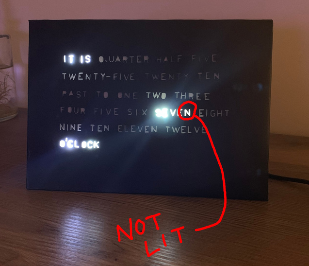
I thought this was a bug in the code loaded onto the Arduino so I plugged the clock into my computer and poked around. What I found made me laugh and facepalm at the same time.
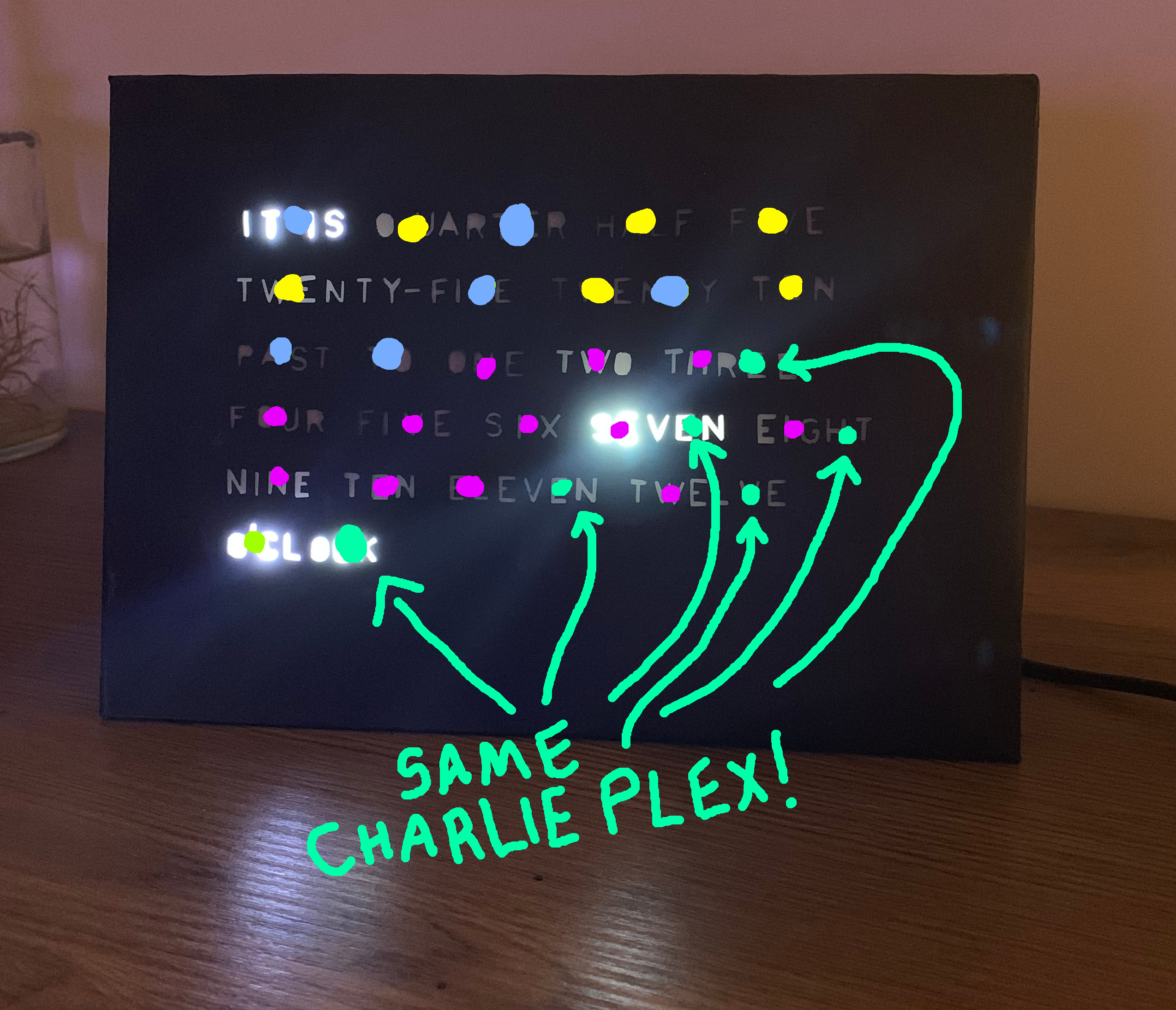
Remember when we learnt earlier on that Charlieplexing is good when you don’t need to light up more than 1 LED at a time? Well, I missed that in all the noise of building the frame and wiring it all together.
In the above image, all of the LEDs marked in turquoise are the “support LEDs”. These LEDs are the ones that were stuck onto a Charlieplex of their own because I added them after I realised some words needed an extra LED or two to light up fully; they weren’t part of the original circuit I breadboarded. What I forgot is that the “o’clock” support LED can be on at the same time as:
- the three support LED
- the seven support LED
- the eight support LED
- the eleven support LED
- the twelve support LED
In short, if it’s three o’clock, seven o’clock, eight o’clock, eleven o’clock or twelve o’clock the support LED for that hour turns off and the support LED for “o’clock” turns on.
Conclusion
Even with all of its faults, I’m really happy with my first sizable electronics project. I learnt a lot and I’m looking forward to building version two.
>> Home